Cracking the Oric hires
May 26th, 2016
During the last few days I’ve spent hours and hours trying to understand how Oric (Oric-1 and Atmos) hires graphics work. Compared to most 8-bit home computers of the 1980s the mode is notably different with its “serial attribute” based layout. If you know how teletext works, you’ll easily notice certain similarities. You can find multiple elaborate explanations of Oric graphics online, but I’ll try and distill their essence into a few minimalistic rules:
- There are 240 by 200 pixels described by 8000 bytes located at A000h (followed by three hard-wired lines of text which we will omit). One row is 40 bytes.
- There are eight colors to choose from: black, red, green, yellow, blue, magenta, cyan and white ie. a typical 3-bit BGR colorspace from 0 to 7.
- For each byte – describing six not eight pixels – you can do one of the following:
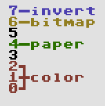
- Change the ink color. Six pixels of paper color will be displayed in this 6×1 block. Byte contents: 0..7.
- Change the paper color. Six pixels of the new paper color will be displayed. Byte contents: 16..23.
- Display pixels using the current ink (1) and paper color (0). Byte contents: 40h + bitmap in the lower-order bits.
- If bit 7 is on, the block will be displayed in inverted colors. Note that the inversion does not affect the result of ink/paper change operations, only the outlook of the 6×1 block. The inversion logic is a bitwise not:
- black – white, 000 – 111
- red – cyan, 001 – 110
- green – magenta, 010 – 101
- yellow – blue, 011 – 100
- Every new row starts with white ink and black paper.
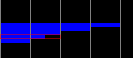
In addition there’s stuff like 50/60 Hz, blinking and text mode setting, but we’ll skip them too. At first the ruleset seems quite simple, but once you actually start thinking of how to do graphics with it, things don’t look that easy anymore. Let’s warm up with a little close-up of a real Oric piccy (“Yessagician” by Dbug):
This is the left edge of the screen and the gray lines denote 6 pixel block borders. How would you choose the operations for displaying the pixels – in particular the area I’ve outlined with a red rectangle?
Solutions: the completely black lines we could show as pixels as the line starts with white ink and black paper, but there’s many other possible solutions too. Every black 6×1 block might actually contain an ink change or perhaps setting the paper to black again. Or setting the paper to white and turning the inverse bit on. The 6×1 blue blocks we could create by simply changing the paper to blue, after which the next identical block could contain an optional ink change.
As to the marked area, however, we need to do something else. Changing the paper to blue on the left leaves us with white/blue which will not do for the next block as there are pixels to be displayed. The only possible solution is to turn paper yellow and invert the colors for both of the blocks. An inverted white/yellow pair provides the needed black/blue for the bitmap.
The first two questions I tried to solve were “Is this picture a legal Oric hires image?” and “How to display a legal image using the possible operations?” There’s more to converting a random image to the Oric, but these two problems have to be understood in order to get anywhere. A first bruteforce solution which didn’t even check all the possible combinations took several minutes to solve just one row of a simple image on a recent i5 computer, so clearly something else had to be done.
For each 6×1 block containing one or two colors there can be multiple solutions. Two-color blocks are the easy case: there’s the bitmap and the colors inherited from the left, possibly inverted. One-color blocks are a different ballgame altogether, since they can contain paper changes, invisible ink changes or they might even be a bitmap. All of this with or without inversion, of course. Another difference is that a two-color block needs to get proper colors from the left, whereas a single-color one can be displayed anytime with a paper change.
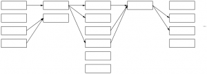
The following image tries to convey a conceptual model of how it works:
Each column in the graph represents a 6×1 block and its multiple possible solutions. Some could call this a directed acyclic graph. The first block can be displayed in four different ways, the next only in two and so on – in reality the numbers are a lot higher with singe-color blocks. The arrows denote possible movement from left to right: each way of displaying a given block here limits the options for the next block. For example a block which leaves ink/paper as white/black does not provide for its neighbor in need of red color.
Instead of a recursive approach starting from the left and trying out all the possible solutions it is enough to simply loop through the columns, create the links, optionally dropping the dead-ends (solutions leading nowhere on the right or with no supply from the left) and duplicates (same in/out combinations). If there is a path that runs all the way from the left edge to the right, we can conclude that this particular row is legal. More than one path is possible, but that doesn’t really matter. Walking back from right to left we can collect one legit representation for the row, thus solving the two “research questions”.
When it comes to dealing with images that do not comply or converting a random jpeg, I don’t have much to say yet. Different approaches will lead to better or worse approximations – as of now I simply turn offending two-color blocks to single-color ones, but much more could be done. Further reading and examples here:
edit: some first thoughs on dealing with non-conforming images. The first thing I’d try is make a graph with approximate solutions, make the errors the weights of the vertices and use a shortest path algorithm such as Dijkstra’s to find the nearest possible approximation.
edit2: here’s a bit more visual representation of the bits as a bonus.


Kommentin kirjoitus
You must be logged in to post a comment.
RSS feed for comments on this post.